Capacitors in Parallel Voltage
10uF C 1 C 2 therefore C 1 C 2 5uF. On the other hand decoupling capacitors are used to stabilize the voltage variations.

Capacitor Circuits Capacitor In Series Parallel Ac Circuits Capacitor Circuit Physics And Mathematics
Parallel and Series Resistor Calculator.

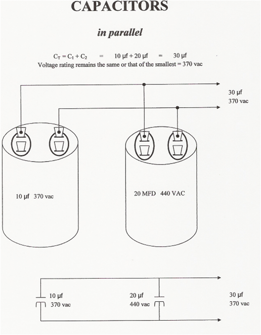
. Voltage divider circuits may be constructed from reactive components just as easily as they may be. Often times the need arises to use several different value capacitors in parallel to target different frequencies or to simply get a higher total capacitance out of many lower ones. The working voltage of a parallel combination of capacitors is always limited by the smallest working voltage of an individual capacitor.
The total capacitance of capacitors in parallel C1C2C3. Energy Stored in a Capacitor. Capacitance equivalent series inductance ESL - the sum of inductive elements including leads a high-resistance DC path Rp in parallel with the capacitance and equivalent series resistance ESR - the series resistive effects combined into a single element.
V is the voltage between the capacitors plates in volts V Capacitance of plates capacitor. For the function of low impedance shunting a single electrolytic capacitor is sufficient but for stabilizing the signal two different types of capacitors are required. Thus if several capacitors rated at 500V are connected in parallel to a capacitor rated at 100V the maximum voltage rating of the complete system is only 100V since the same.
The analogous result for parallel capacitors comes from Q VC the fact that the voltage drop between all parallel capacitors or any elements in a parallel circuit is the same and the fact that the charge on the single equivalent component will be the total charge of all the individual. If an individual capacitor within a bank of parallel capacitors develops a short the entire energy of the capacitor bank. Tube amp power supplies often make use of capacitors in series or parallel for a multitude of reasons.
However its possible that the lower rails diode wont like being reverse biased so much and any capacitors may not be rated for the higher voltage definitely a possibility given the extremely competitive. So the more you increase or decrease the voltage source in a circuit the more or less charge that your capacitor will have. Parallel Combination of Capacitors When capacitors are connected in parallel the potential difference V across each is the same and the charge on C 1 C 2 is different ie.
For two identical parallel connected capacitors having the same combined capacitance of 10uF as the original C above equals. Parallel combination and Series combination. Q C1 VC 1 10 x 5-6 005mC of charge on its plates and Q C2 VC 2 10 x 5-6 005mC of.
Deduce the rules for combining conductances. The capacitor equivalent circuit comprises four elements Figure 1 right. When capacitors are connected in parallel the total capacitance is the sum of the individual capacitors capacitances.
2The raw materials acquisition stage and production stage are further backtracked according to capacitors compositions and their. It follows that resistors in parallel have the same voltage across their respective terminals. Equivalent Capacitance of Parallel Capacitors.
Capacitance in Parallel and Series Circuits. For two conductances and in parallel the voltage across them is the same and from Kirchhoffs current law KCL the total current is. The total capacitance is the sum of each capacitors value used in parallel.
Resistors are in parallel when they are connected between the same two nodes. When you place capacitors in parallel in a circuit you can find the total capacitance. All three have a claim to making the first primitive capacitor.
The different parallel current paths leading from one node to another are called branches and a branch can consist of one or multiple resistors. Consider the two capacitors C1 and C2 connected in series across an alternating supply of 10 volts. Capacitor Types and Capacitance.
C 2 1uf and C 3 01uf So C T 47 1. American scientist and statesman Benjamin Franklin 17061790 experiments with connecting Leyden jar capacitors in series while Polish mayor and physicist Daniel Gralath 17081767 and German Johann Heinrich Winkler 17031770 investigate using them in parallel. The ceramic capacitor derating voltage should be at least 50 of the expected voltage to ensure risk-free operation.
Some designers will use this arrangement to allow for the voltage drop across the capacitors to be able to use lower voltage rated. As these capacitors are connected in parallel the equivalent or total capacitance will be equal to the sum of the individual capacitance. C T C 1 C 2 C 3 Where C 1 47uf.
If two or more capacitors are connected in parallel the overall effect is that of a single equivalent capacitor having the sum total of the plate areas of the individual capacitors. As the two capacitors are in series the charge Q on them is the same but the voltage across them will be different and related to their capacitance values as V QC. Higher the voltage across it c lager.
If you put the 5V and 12V in parallel the voltage would be somewhere in between depending on the internal resistance of each source. In the below circuit diagram there are three capacitors connected in parallel. The capacitance C of the plates capacitor is equal to the permittivity ε times the plate area A divided by the gap or distance between the plates d.
Placing a capacitor in parallel with a resistor reduces high-frequency EMI. The supply voltage V is common to both parallel connected capacitors thus. The voltage across each capacitor in this configuration is common.
One is that the maximum rated voltage of a parallel connection of capacitors is only as high as the lowest voltage rating of all the capacitors used in the system. Example for Parallel Capacitor Circuit. For tantalum capacitors a DC bias voltage of 11 to 15 V for types with a rated voltage 25 V or 21 to 25 V for types with a rated voltage of 25 V may be applied during the measurement to avoid reverse voltage.
Two equations can be used to find the total capacitance of these circuits. This capacitors in series calculator helps you evaluate the equivalent value of capacitance of up to 10 individual capacitorsIn the text youll find how adding capacitors in series works what the difference between capacitors in series and in parallel is and how it corresponds to the combination of resistorsIf you want to familiarize yourself with the. Ceramic capacitors are often used in electronic circuits due to characteristics such as precision tolerance size.
Two frequently used methods of combination are. The system boundary for the entire life cycle of high-voltage AECs encompasses four stages including raw materials acquisition stage production stage use stage end-of-life stage and the transportation between the stages see Fig. Use DigiKeys Voltage Divider conversion calculator to quickly and easily determine the output voltage of the divider circuit given the input voltage and resistor values.

Capacitors In Series And Parallel General Physics 2 Studying Amino Amino Physics Notes Engineering Notes Physics And Mathematics
Capacitors In Series Capacitors In Parallel Examples Electronics Area Capacitors Electrical Engineering Series

Combination Of Capacitor Infographic Physics Lessons Physics Classroom Physics
Parallel Wiring Capacitors Capacitor
No comments for "Capacitors in Parallel Voltage"
Post a Comment